Decided to build my own forced airflow solution for my convectors around the house. There's commercial options too, but these use too small fans with too high rotational speed, and provide nowhere near the airflow I would like to see.
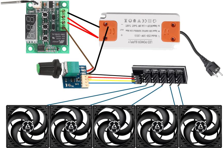
Forced airflow
Lower heating water temperatures makes your central heating boiler more efficient, and heat transfer in your convectors and radiators lower.
So low, that you can have trouble keeping the ambient temperature high enough for comfort.
Physics interlude: What makes air flow
As a wee boy during my Chemical Engineering bachelor, I was tasked with figuring out if the factory I was working at had sufficient natural airflow. Inside the factory, hydrogen and nitrogen were used and Health & Safety wanted to know if any leaked gasses would be evacuated fast enough. The factory hardened vegetable oils for use in margarines etc. There were quite some heat generating reactors, filtration units and other equipement that generated a lot of heat.
Theoretical natural ventilation is dependent on 2 factors:
- Aperture (area of ventilation)
- Temperature difference
and linearly. So, double the temperature difference, double the airvolume. No safety issues in that factory by a large margin, the roof had sufficient area and temperature difference was plenty.
A central heating system works most efficiently when the temperature difference between the heating substance (hot air) and the heating water is as high as can be. Thus you can improve your central heating boilers's efficiency by decreasing the outlet temperature.
See what we're doing here? We're making the natural airflow from the convectors (and radiators) lower for efficiency. Lower water temperature means less temperature difference with the ambient temperature and thus lower airflow, slower heating, ... Brrr...
Forced airflow to the rescue!
Forced airflow
Commercial solutions for forced airflow exist, e.g. SpeedComfort but these seem sub-optimal for the use. I see ca. 60mm fans in the assembly and I worry about noise or low airflow. Then again, they are simple to install. Pick your poison!
As it took me quite some time finding all parts, let me try saving you some!
Components
| Item | Shop | €/pc. | pcs. |
|---|---|---|---|
| Arctic P14 PWM 5pcs. | Alternate | 36.99 | 2 |
| Arctic P12 PWM 5pcs. | Alternate | 29.99 | 1 |
| DC 12V Transformer LED Power Supply 18W | Aliexpress - SeeSensor store | 2.16 | 4 |
| 2pcs XH W1209 LED Display Digital Thermostat with NTC Probe and case | Aliexpress - UMLIFE Store | 3.54 | 2 |
| DC5-12V Manual 4-Wire PWM Fan Speed Controller | Aliexpress - SeeSensor store | 1.05 | 4 |
| 1 to 5 Way PWM Fan Hub PC 4-PIN | Aliexpress - Cylarix PC Acc. | 2.56 | 3 |
Details on why these parts were chosen below. I'm starting with the fans as the power draw of the fans determines the minimum spec of other components. Then I walk through in order power-outlet (110 or 220V) to fan.
Arctic P14 and P12 fans
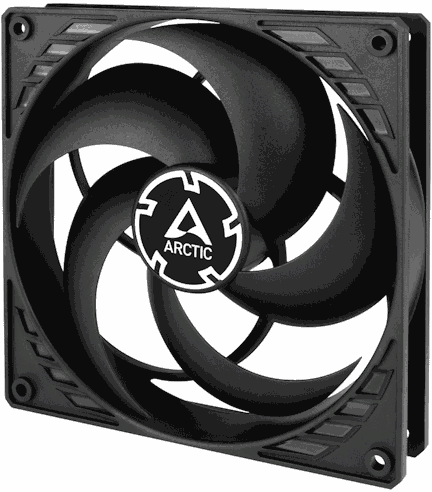
These are easy to come by and, especially in the 5pcs bulk kits, relatively cheap. Arctic is a well known brand in PC components and known for their low-noise products. These fans also have good static pressure: a convector has many thin plates for heat-transfer, but this increases the drag. More static pressure means you'll get closer to the theoretical capacity of the fan with the drag. These fans at max speed (1700-1800rpm) generate a massive amount of airflow: over 600m³/hr (just shy of 500 for the 120mm). At lower speeds, these fans will be inaudible whilst still providing plenty of airflow. Maximum power-draw at 12V per 140mm fan is 0.15A, for the 120mm fan it is 0.09A.
I set out using non-PWM (Pulse Width Modulation) fans and controlling fanspeed with voltage as the non-PWM versions are a bit cheaper. I couldn't find a cheap variable voltage output powersupply or controller. So PWM fans it is!
12V power-supply
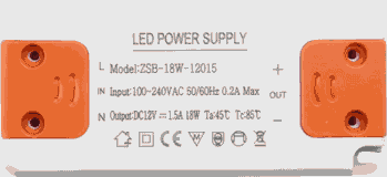
The 140mm fans use 0.15A each, if we need to power 5 of them we need 0.75A. At 12V that's 8W of power used by the fans, and some extra by the fan-controller. Theoretically you could do with the 12W version, but I chose 18W for a bit of headroom.
The ones I selected are cheap and not bulky. They're listed for LED lights, which is also a PWM application.
| Terminal | Connected to |
|---|---|
IN |
Wall outlet |
OUT + |
Digital thermostat +12V and K0 terminals |
OUT - |
Digital thermostat GND and Fan controller black wire - |
Digital thermostat relay
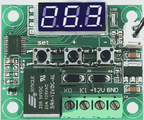
The fans only need to run if the inlet of the convector reaches a certain temperature. This W1209 unit is very common and can be found in many shops on Aliexpress and elsewhere. I was focussing on the 12V, but 220V units also exist. Using a 220V item would allow you to place the thermostat before the 12V power-supply, potentially reducing the power-loss. Checking again, I see that the 110-220V units simply have an on-board 12V supply with it's own idle power-draw.
The power-supply positive terminal connects to two of the terminals on the relay. It is both the power-supply for the relay (+12V terminal), as well as the source for the switched terminal (K0 terminal). The power-supply negative terminal connects to the GND terminal on the relay. The K1 terminal is the switched 12V input for the fan controller.
| Terminal | Connected to |
|---|---|
+12V |
12V Power supply Out + |
GND |
12V Power supply Out - |
K0 |
12V Power supply Out + |
K1 |
Fan controller red wire / + |
Fan controller
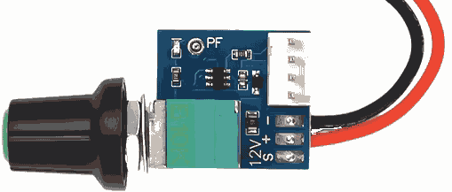
Pulse-With-Modulation fans have an additional wire, making it a 4 not 3 pins in use. This is the "modern" way of controlling rotation-speed of fans. Your PC, laptop, etc. use this to control the fan-speed (and noise!).
We will connect only the red (+) and black (-) terminals of the controller. The yellow wire is the tachometer signal which we have no use for. The controller can handle 4A, ample enough for our fans.
| Terminal | Connected to |
|---|---|
12V + |
Digital thermostat K1 |
12V - |
12V Power supply Out - |
12V S |
Not connected |
| Molex KK 4-pin | Fan hub cable |
5-way fan hub 4-pin

At first I was looking for splitter cables, but I've not found any with more than 3 outputs. Double splitting seems messy with lots of wires. The cables on the fans are 40cm long, with 5 140m fans the max distance is 70cm so we can reach a central point from all fans.
This is a passive device, anything on the cable connector is passed on to all the 5 Molex KK outputs.
| Terminal | Connected to |
|---|---|
| Cable | Fan controller Molex KK 4-pin |
CPU |
Fan #1 |
FAN1 |
Fan #2 |
FAN2 |
Fan #3 |
FAN3 |
Fan #4 |
FAN4 |
Fan #5 |
Planning assembly.
I have a plan, components are ordered. Whilst I wait for the components to arrive, I was thinking about assembly.
Just about all connections are screwed or simply a connector.
The only connection that's not trivial is the thermostat to the fan controller.
It is likely that the fan controller has a 3-pin Molex KK (fan) connector.
I'll probably snip off that 3-pin connector and insert the red + and black - wires directly into the GND and K1 terminals of the thermostat.
Pictures to follow!

